
Top-runner Energy Saving Type
The performance of energy saving is more than top-runner standard value
The example of three phases 1,000kVA equivalent load factor 50% (ratio of our company)
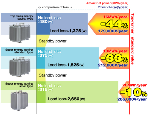
*Top-runner system (Definition)
The top-runner system provides higher efficiency based on existing products with excellent with excellent efficiency and in view of prospects in technical development.
Significant decrease of emission of carbon dioxide
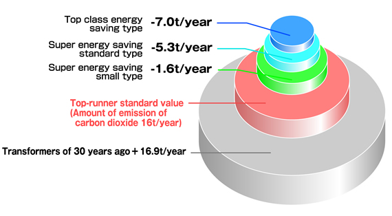
The energy saving effect is greatly different based on the load factor
For Super Amorphous X Series, because of the low no-load loss and extremely low standby Power requirement, the high energy saving effect that suitable for the reality is demonstrated.
| Receiving Voltage |
Data No. |
1 Year AverageEquivalent Load Factor (%) |
Contracted Power Ratio(%) |
Weighted Average Load Factor in Contracted Power Ratio (%) |
||||
|---|---|---|---|---|---|---|---|---|
| Day time | Night time | 1 Day | Day time | Night time | 1 Day | |||
| Extremely High |
210 | 47.3 | 32.2 | 16.7 | 40 | 40.8 | 24.1 | 33.6 |
| High Voltage |
80 | 35.9 | 40.5 | 28.0 | 60 | |||
Reasons for super energy saving and highly effectiveness
The merit of amorphous is applied to the core of transformers.
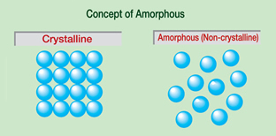
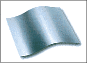
The merit of amorphous is applied to the core of transformers. The amorphous is a non-crystal substance created by rapidly freezing liquids of high temperature. Because there is no rule of atomic arrangement, the energy loss (hysteresis loss) is little when the flux of magnetic induction passes the iron core. Moreover, eddy current loss is decreased because the thickness is approximately 0.03 mm which is about 1/10 comparing with silicon steel . Therefore, the no-load loss (eddy current loss and hysteresis loss) can be decreased to about 1/5 compared with silicon steel.
Amorphous
The load loss and no-load loss occur at the same time when the transformer is operated, the loss is a useless output chiefly converted into heat.
The loss occurs because of the flow of load current when loaded and it is in proportion to the second power of size of load.
The constant loss that always occurs when in the state of receiving power regardless whether loaded or not.
Environmental-friendly transformers
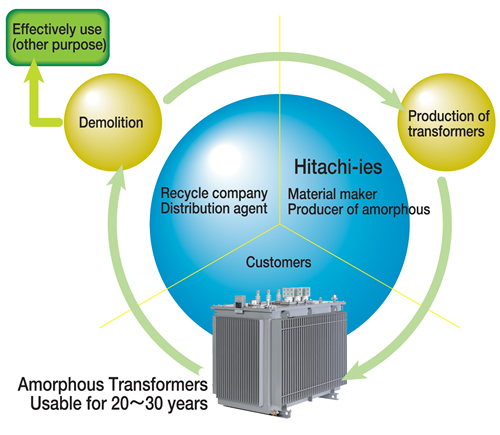
Recycling concept of amorphous
| No. of phases |
Rating Capacity (kVA) |
Frequency | Voltage Specification | Connection | Standard | |
|---|---|---|---|---|---|---|
| Primary (V) |
Secondary (V) |
|||||
| 6kV Standard Model 200V class | ||||||
| Three | 300, 500 | 50 or 60 only |
F6,750-R6,600-F6,450-F6,300-6,150 | 210 | JEC 2200-1995 JEM 1482-2005 |
|
| 750, 1,000 |  |
|||||
| 6kV Standard Model 400V class | ||||||
| Three | 1,500, 2,000 | 50 | F6,750-R6,600-F6,450-F6,300-6,150 | 420-242 | (The second |
JEC 2200-1995 JEM 1482-2005 |
| 1,500, 2,000 | 60 | 440-254 | ||||